Are you searching for an 3D scanner for an upcoming project? We understand that it can be quite difficult to find the ideal solution that suits your specific needs. This article will guide you through the significance of the field of view in a 3D Scanner, methods to compare various models of 3D scanners, and other essential factors to consider when selecting the perfect 3D scanner for your project.

What is the Field of View of a 3D scanner?
The field of view (FOV) of a 3D scanner refers to the area or volume that the scanner sensor can capture in a single scan. It represents the extent of the physical space that the 3D scanner sensor can “see” and acquire data from. All structured light scanners including white light and blue light scanners operating under these principals of working distance and field of view.
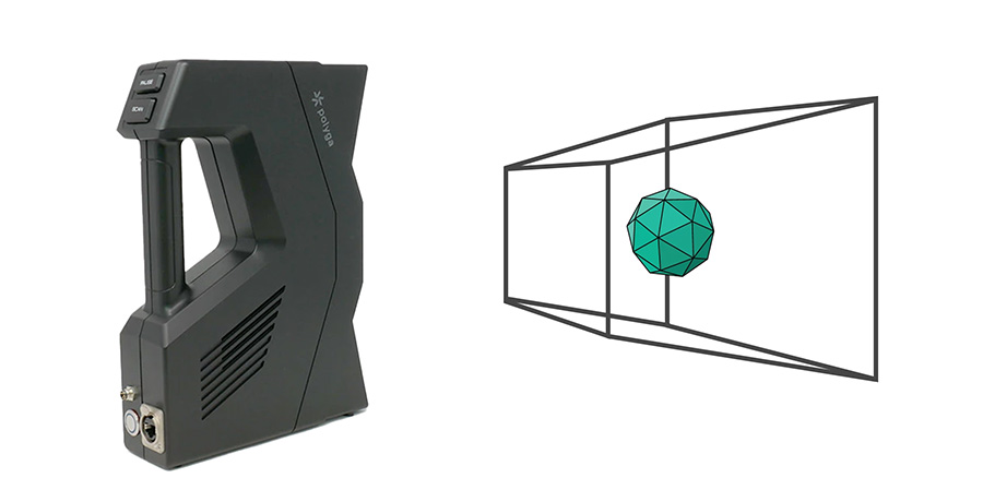
Figure 1. The field of view (FOV) of a 3D scanner
The FOV of a 3D scanner can vary depending on the type and design of the scanner. It is typically described in terms of dimensions such as width, height, and depth, or it can be represented as an angular measurement. The FOV can be different for each axis, and it determines the maximum size entire area or volume of objects that can be scanned in a single scan operation.
For example, a handheld 3D scanner might have a FOV of approximately 300 mm x 200 mm x 200 mm, which means it can capture objects within that physical volume. On the other hand, a stationary 3D scanner or large-format 3D scanner used for scanning rooms or buildings may have a larger FOV, of several meters in width, height, and depth.
It’s important to consider the FOV of a 3D scanner in relation to the size of objects or scenes you plan to scan. If your objects are larger than the scanner’s FOV, you may need to perform multiple scans and stitch them together using software to create a complete 3D model.
When comparing different 3D scanners, it’s advisable to consider not only the FOV but also the accuracy, resolution, and other specifications to ensure that the scanner meets your specific project requirements.

Figure 2. The depth of field and field of view
This diagram illustrates the field of view of a 3D scanner. The center depth of focus is where the scan object should be placed in order to get optimal results to get the best focus and accuracy. The Z-Near is the starting point of the scanning volume. The Z-Far is the furthest distance that the scanner can scan.
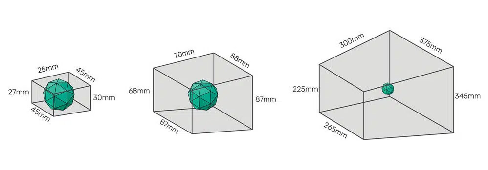
Figure 3. Field of view Polyga 3D Scanners
Using Polyga scanners as an example, the Compact S1 has a small to medium field of view compared to the Compact L6. This means that the Compact S1 is a better scanner for scanning smaller objects, while the Compact L6 is better suited for scanning medium to large objects.
What happens when the field of view of the scanner is too small to scan a large object?
Picking the right field of view is about finding the right balance between having enough detail and accuracy for the range of objects you are looking to scan, while providing a decent amount of coverage so you don’t have to take too many scans for the object when you are scanning small objects.
Incomplete Coverage: When you scan a large object with a 3D scanner that is optimized for scanning small objects, you would have to take more scans to create a full digital 3D model than one with a larger field of view. This can become a very labor intensive and time-consuming process. More time would be required to clean up the individual scans as well as merging all the individual scans into a full 3D model.
The example below illustrates the difference between using a smaller field of view scanner versus a larger one for the same scanning object.
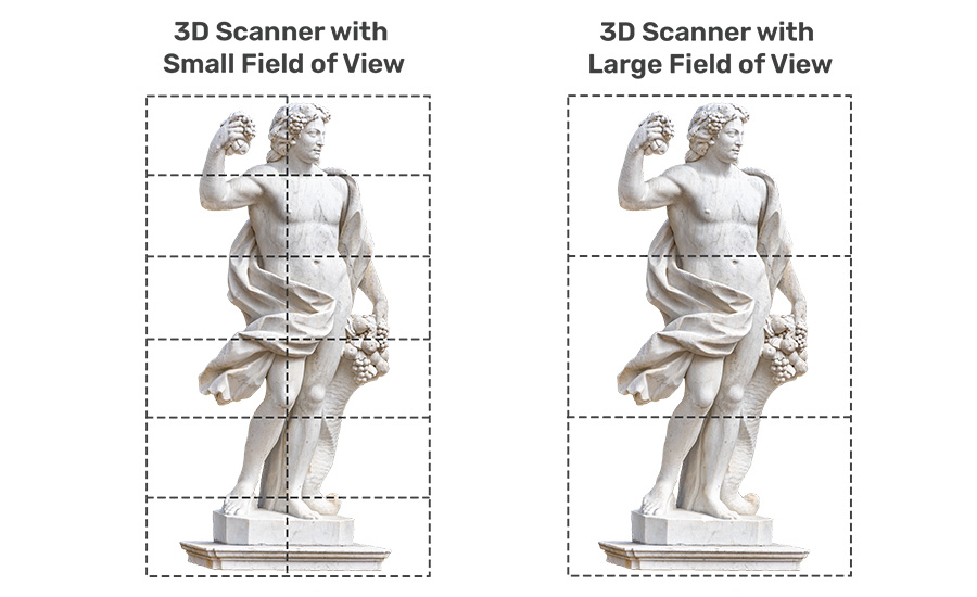
Figure 4. Difference between field of view
The number of sections denotes the number of scans that are needed to complete the geometry of the same objects using different scanners. As you can see with the challenges below:
Loss of Detail and Accuracy: Scanning a large object in multiple passes introduces the possibility of misalignment between the individual scans. Misalignment can lead to a loss of detail and accuracy in the final 3D model, especially at the seams where the scans are merged. It may require manual adjustment or registration techniques to align the scans correctly and minimize discrepancies.
Distortion and Noise: In some cases, the FOV limitations may result in distortions or noise in the captured data, particularly at the edges of the individual scans. These issues can affect the overall quality and accuracy of the final 3D model.
To mitigate these challenges, it’s important to plan your scanning approach carefully choose your 3D scanner when dealing with a large object and a scanner with a small FOV. Consider using reference markers or targets to aid in the alignment of the individual scans. Additionally, selecting a scanning method that ensures overlap between adjacent scans can improve the stitching process.
If you frequently work with large objects, you may want to consider using a 3D scanner with a larger FOV or exploring alternative scanning techniques such as photogrammetry, mobile scanning systems, or wider camera lenses that can handle larger volumes in a single capture. These solutions can provide more efficient and accurate results for scanning large-scale objects.
What happens when the field of view of the scanner is too large to scan a smaller object?
If you are scanning an extremely small or smaller objects with intricate details and texture information, using a 3D scanner with a large field of view will lose much of the fine geometry details and scan accuracy will not be the best. When you use a 3D scanner with a large field of view (FOV) to scan an extremely small object, you may encounter a few considerations and challenges:
Reduced Detail and Resolution: Scanning small objects within a large FOV can result in reduced scan detail, scan accuracy and resolution in the captured data. The 3D scanner may not be able to capture fine details or small features of the object with the same level of precision as a scanner specifically designed for smaller objects. This reduction in detail can impact the overall accuracy and quality of the resulting 3D model.
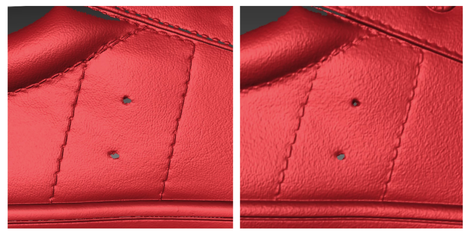
Figure 5. Resolution difference between the S1 – Standard(smaller field of view) and the S1 – Wide(larger field of view)
Increased Noise and Distortion: Scanning a small object within a large FOV 3D scanner can introduce more noise and distortion into the captured data. The 3D scanner may pick up irrelevant background information or environmental factors that affect the quality of the scan. These factors can include variations in lighting, reflections, or interference from nearby objects.
Alignment and Registration Challenges: When scanning a small object within a large FOV, it can be challenging to accurately align and register the object within the scan data. The software used for post-processing and aligning the scans may struggle to accurately match the small object with the larger scanned scene. This can lead to misalignments and inaccuracies in the resulting 3D model.
Longer Processing Time: Scanning a small object within a large FOV may result in a larger dataset, which can increase the processing time required for aligning, cleaning, and generating the final 3D model. The larger dataset may require more computational resources and time-consuming post-processing software steps.
To address these challenges, there are a few techniques you can consider:
Use markers or targets: Placing markers or targets on the small object can help with alignment and registration. These markers provide reference points that assist in accurately positioning and aligning the small object within the larger scan.
Utilize a 3D scanner with a variable field of view: Some 3D scanners like the Polyga CarbonX have the capability to change its field of view based on the size of the objects that need to be scanned. By having a small field view for small objects, you can achieve higher resolution and accuracy.
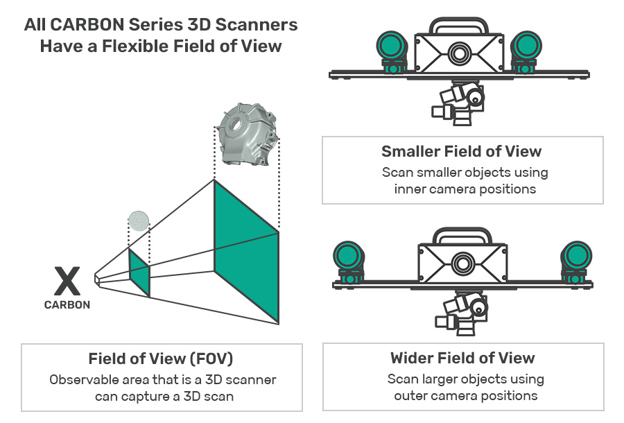
Figure 6. Flexible field of view – Carbon series
Optimize scanning parameters: Adjusting the scanning parameters such as resolution settings, exposure settings, or scanning distance can help optimize the scan for small objects within a large FOV. Experimenting with these parameters and finding the optimal settings for your 3D scanner can improve the results.
Consider alternative scanning methods: For extremely small objects, other scanning methods like microscopy-based scanning or specialized camera macro lenses might be more suitable. These methods are specifically designed for capturing small objects with high detail and resolution.
By considering these factors and employing appropriate techniques, you can mitigate the challenges associated with using a 3D scanner with a large FOV to scan an extremely small object and improve the quality and accuracy of the resulting 3D model.
It’s important to consider the FOV alongside other factors like accuracy, resolution, scanning speed, and application suitability when selecting the 3D scanner for your specific needs.
And there you have it. We hope that this article has been helpful to you.
And, if you have any other questions about what type of 3D scanner is right for your project,
feel free to send them to our sales team at sales@polyga.com, and they will be happy to help.
Best regards,

Manu Moncy
Polyga Inc.
Vancouver, British Columbia, Canada
Email: mm@polyga.com
Website: Polyga.com