Tips & Tricks: Hidden Features of Xtract3D Plugin for Solidworks
What is Xtract3D?
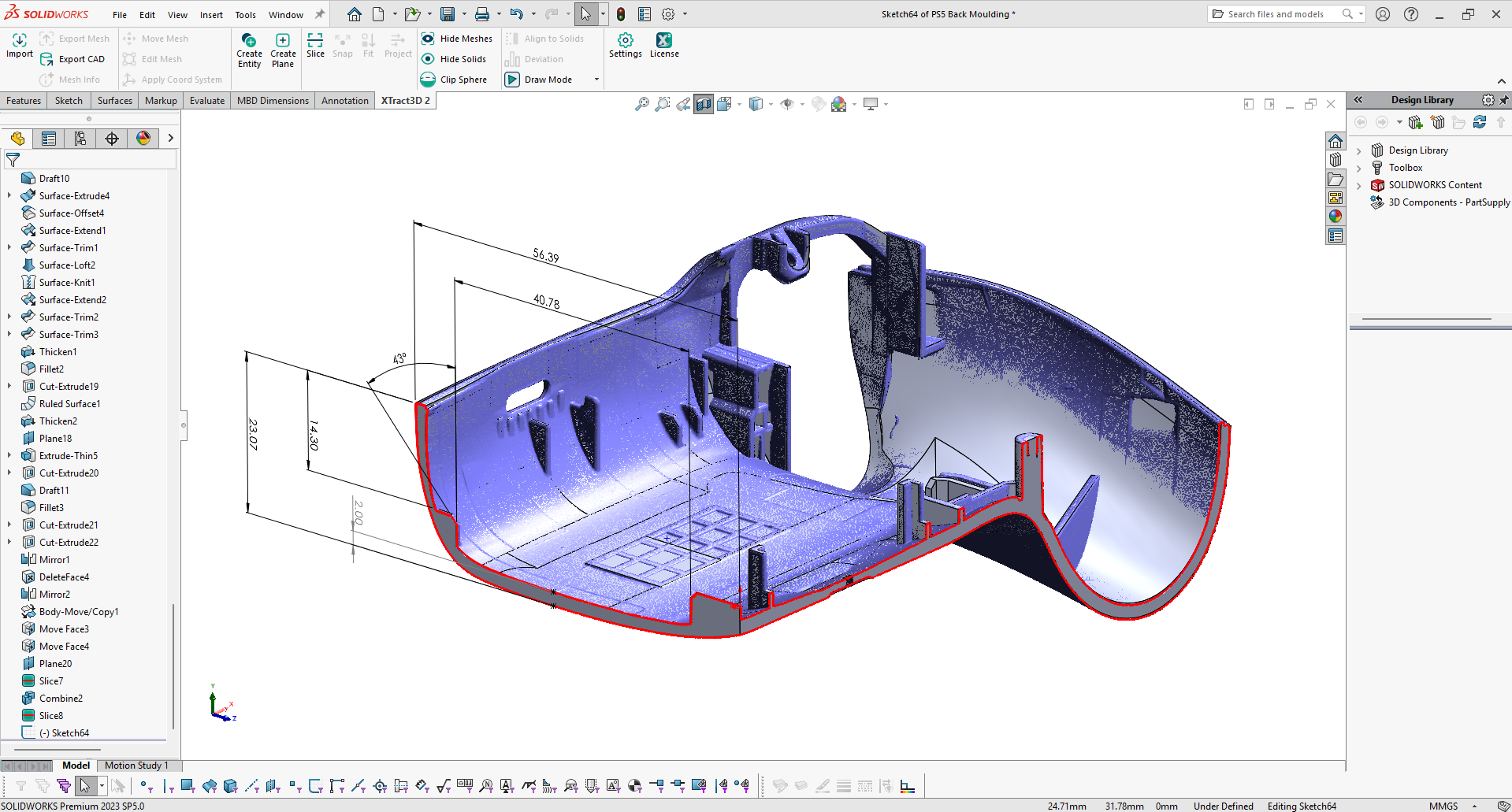
Xtract3D is a 3D scanning application toolbar plugin designed to work natively inside SOLIDWORKS. It simplifies the complicated process of reverse-engineering by importing your 3D scan data or mesh data directly from a 3D scanner; essentially a scan to CAD reverse engineering plug in or add in for solidworks.
Introduction
In this article we’ll explore the hidden Features of Xtract3D Plugin when working with 3D scan data from parametric CAD models models. The plugin supports working with large datasets of mesh or point cloud 3D scan data, advanced feature extraction capabilities and precise curve fitting techniques. Follow along and become a scan to CAD pro in no-time.

Beyond all the tools fundamental functionalities, Xtract3D also offers supplementary tools and features that enhance workflow efficiency, particularly catering to more challenging scenarios and special requirements, which includes:
Xtract3D Plugin for Solidworks
- Lesson 1: Working with Large Point Cloud Data & BIM
- Lesson 2: Reorienting Mesh / Point Cloud
- Lesson 3: Quality Inspection of CAD Drawing
Lesson 1: Working with Large Point Cloud Data & BIM
What is BIM?
BIM stands for Building Information Modeling which is a process of creating and modelling business information on a construction project across the project lifecycle. It is crucial to the planning, design, and construction of structures and buildings.

Figure 1.1 BIM or Building Information Modeling
In the field of BIM and many reverse engineering software re-engineering projects, it’s common to work with massive .e57 and .las point clouds. However, dealing with these sizeable datasets often leads to slow processing time and sluggish rendering.
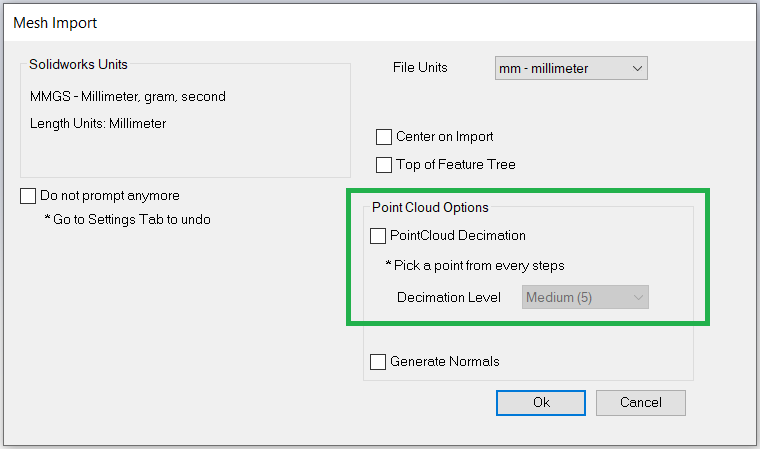
Figure 1.2 Importing Large Data Sets Prompt Window
Working with Large Data Sets
While importing large data sets, it is possible to decimate the point cloud data which basically reduces the point cloud density. This helps improve the sluggish rendering issues that are often associated with large point cloud data in the SolidWorks platform as well as other 3D scanning applications. Checking the ‘PointCloud Decimation’ option lets users select a preferred decimation level or customize it according to their needs.
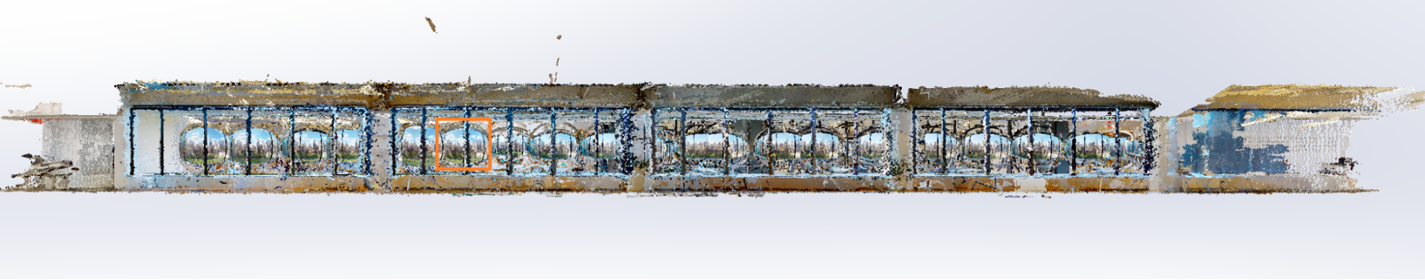
Figure 1.3 Above is a comparison of details on a point cloud sized approximately at 6GB, before and after varying degrees of decimation

Figure 1.4 Original

Figure 1.5 Decimation Level 2 – Point Density 1/2

Figure 1.6 Decimation Level 3 – Point Density 1/3

Figure 1.7 Decimation Level 5 – Point Density 1/5
Lesson 2: Reorienting Mesh / Point Cloud
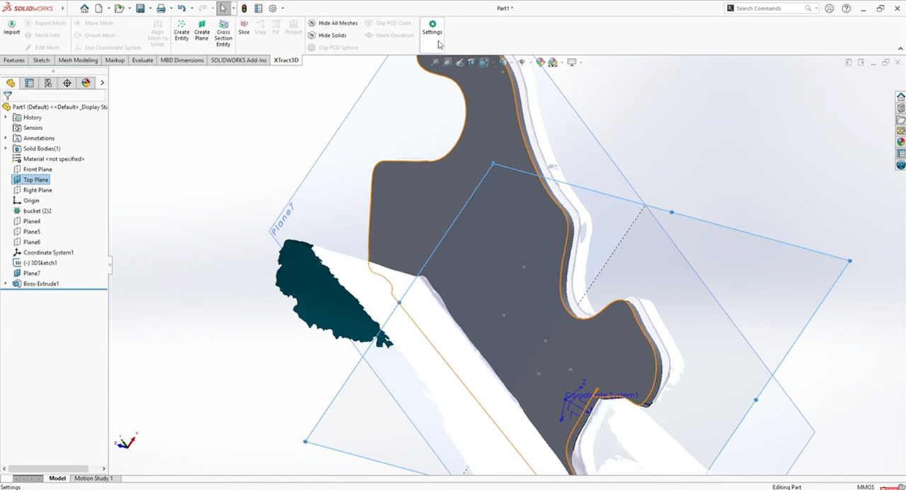
When working with 3D spaces and augmented reality, it is sometimes needed to change the file orientations which can be quite challenging. Xtract3D’s “Orient Mesh” function comes in handy here. It helps align mesh and scan data’ orientations, making them more manageable for further work.
Illustrating this with an example, consider the bullet scan data shown in image 2-1. The angle formed between the bullet and the top plane introduces challenges when attempting to extract meaningful cross-sectional slices for some reverse engineering applications. In contrast, the orientation depicted on the right is more favored for this purpose.
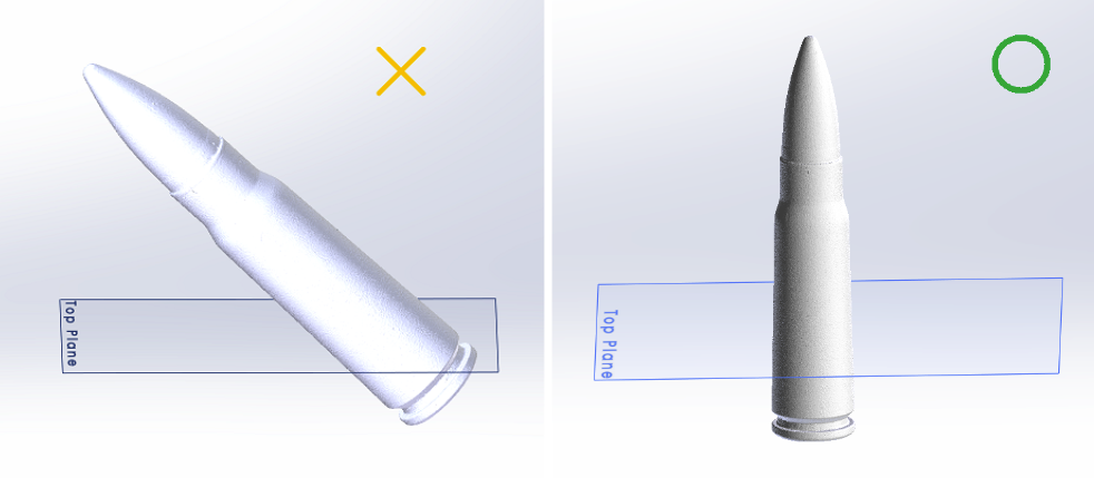
Figure 2.1 Original Orientation Versus Desired Orientation
Steps to Change Orientation Below
- Step 1: Create the source plane by choosing multiple points.
- Step 2: Assign target plane – in this example, the top plane
- Step 3: Click “Rotate Source to Target” button
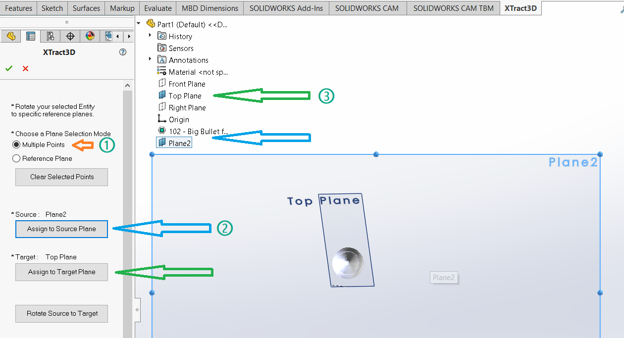
Figure 2.2 Step-by-Step Illustration
In case there is a misalignment between the part creating a CAD model drawing and the mesh, ‘Align Mesh to Solids’ can be a useful tool.
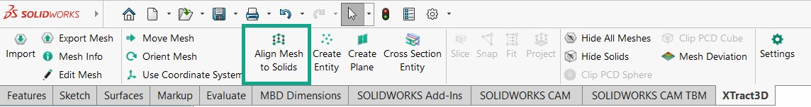
Figure 2.3 Align Mesh to Solids
This basic toolset employs a 3-point alignment methodology. The steps are similar to that of the Orient Mesh tool:
- Step 1: Choose three points on the mesh. These points should not be in a straight line or form an Equilateral triangle, ensuring a successful alignment.
- Step 2: Select three corresponding points on the CAD drawing that match the chosen locations on the mesh.
- Step 3: Rough Align performs a preliminary alignment using the selected points, followed by Fine Align to minimize the deviation between meshes.
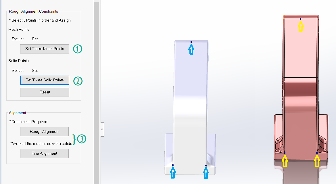
Figure 2.4 Step-by-Step Illustration
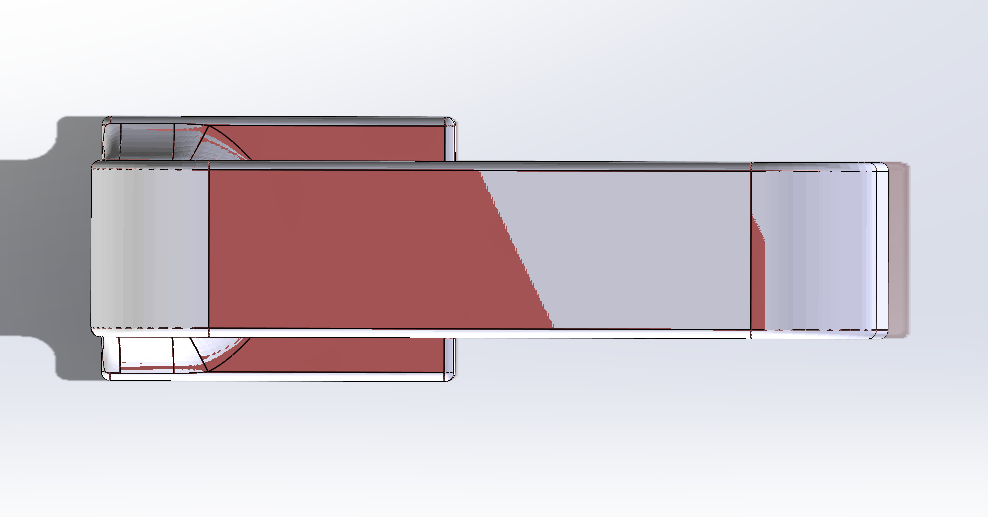
Figure 2.5 Alignment Result
Lesson 3: Quality Inspection of CAD Drawing
Upon the completion of the entire reverse engineering workflow process for a component, there arises a need to assess the quality of the accomplished reverse engineering task. The Mesh Deviation tool is accessible for this reverse engineering purpose.
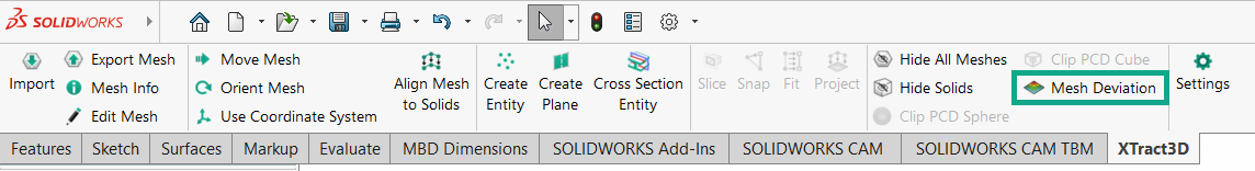
Figure 3.1 Mesh Deviation Tool
With the tool activated from the toolbar, the interface as shown below will be presented. The four colored bars enable users to specify the error tolerance, maximum error, and minimum error.
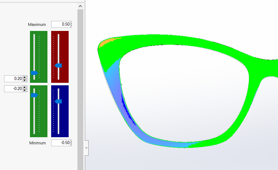
Figure 3.2 Mesh Deviation
The deviation between the two surfaces will be illustrated by a color map – Areas falling within the tolerance will be represented in green, while positive deviations will appear in yellow and negative deviations in blue.
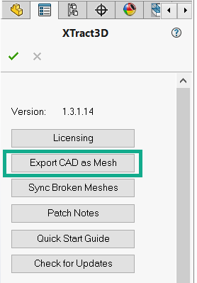
Figure 3.3 Converting CAD to Mesh
When there is a requirement to import a CAD model for drawing into a third-party mesh inspection software, the Export CAD as Mesh function becomes highly practical.
While the question may arise as to why one should opt for Xtract3D’s exporting capabilities when Solidworks already offers support for exporting both CAD models and drawings across more than 20 file formats, the scan data to create following comparison provides valuable insights:
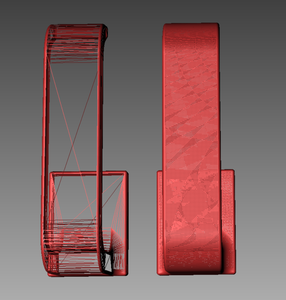
Figure 3.4 Solidworks Export as STL file (Left) and Xtract3D Export as Mesh Result Comparison
Beyond the convenience of a two-click conversion process, the difference between the resulting meshes is evident. When observing them in wireframe mode through FlexScan3D – Polyga’s dedicated 3D scan and mesh inspection software, while the exported mesh from Solidworks is characterized by its minimal vertex count, the Xtract3D export contains evenly distributed vertices. This can be particularly beneficial for a thorough mesh examination.
While it’s tempting to download a 3D scanning app from an iphone mobile device or android device, these free versions of 3D scanning software often don’t have the post processing tools required to to properly manipulate and process the scan objects correctly. Other scanning methods such as augmented reality scanning apps, laser scanning, and lidar sensor technology all provide their own challenges to users.
Conclusion
We hope that this article provides you with some useful information by addressing some of the challenges engineers may encounter when working on scan to CAD reverse-engineering projects, and interesting features and solutions to each of them. Currently there isn’t a free version of Xtract3D scanning app but there is a free trial available here. https://www.polyga.com/xtract3d/free-trial/ If you have more questions about Xtract3D; whether your experienced with CAD models user or a new user of the reverse engineering software, please feel free to contact us at support@polyga.com, and we are more than willing to provide you with assistance and support.
I hope that this article is helpful to you on your 3D scanning journey.
And, if you have any other questions about what type of scanner is right for your project,
feel free to send them to our sales team at sales@polyga.com, and they will be happy to help.
Best regards,
River Zhang
Polyga Inc.
Vancouver, British Columbia, Canada
Email: contact@polyga.com
Website: Polyga.com