

Reverse Engineering 101: Step-by-Step Guide to Creating Parametric CAD from 3D Scan Data
Sometimes you don’t have access to a part’s original design documentation from its original production. Reverse engineering empowers you to analyze a physical part and explore how it was originally built to replicate, create variations, or improve on the design. The goal is to ultimately create a new CAD model for use in manufacturing.
While the concept of reverse engineering is quite simple, most people don’t have a good grasp of the step-by-step workflow on how to create CAD from 3D scan data.
What does the reverse engineering workflow look like at a glance?
The first part of the process involves using a 3D scanner to collect the geometric surface measurements of an existing part quickly and accurately. Calipers and hand tools have traditionally been used to take measurements. However, they are often proven limiting when trying to measure complex parts with complicated features (e.g. organic surfaces).
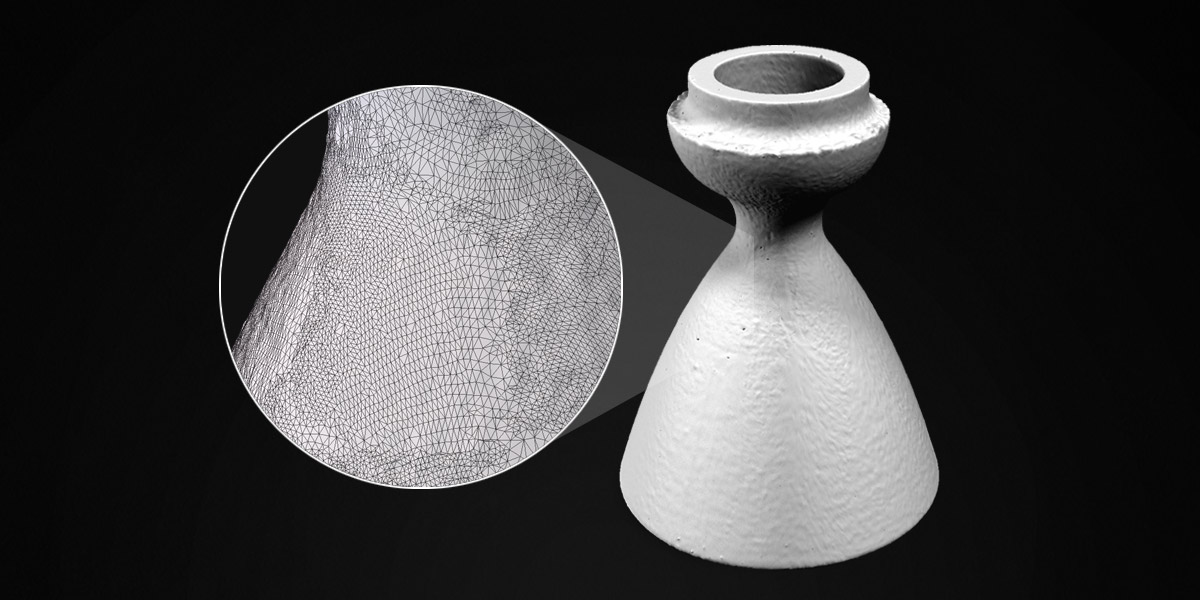
The scanner typically outputs 3D scan data as dense triangle mesh in obj, ply, or stl mesh formats—anywhere from a few thousand to millions of polygons.
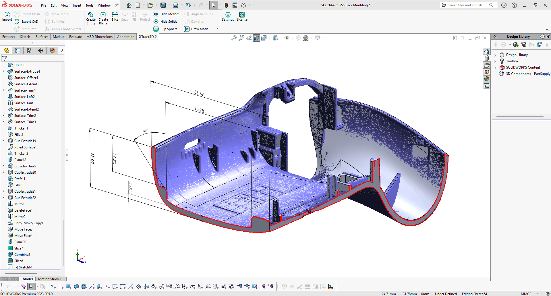
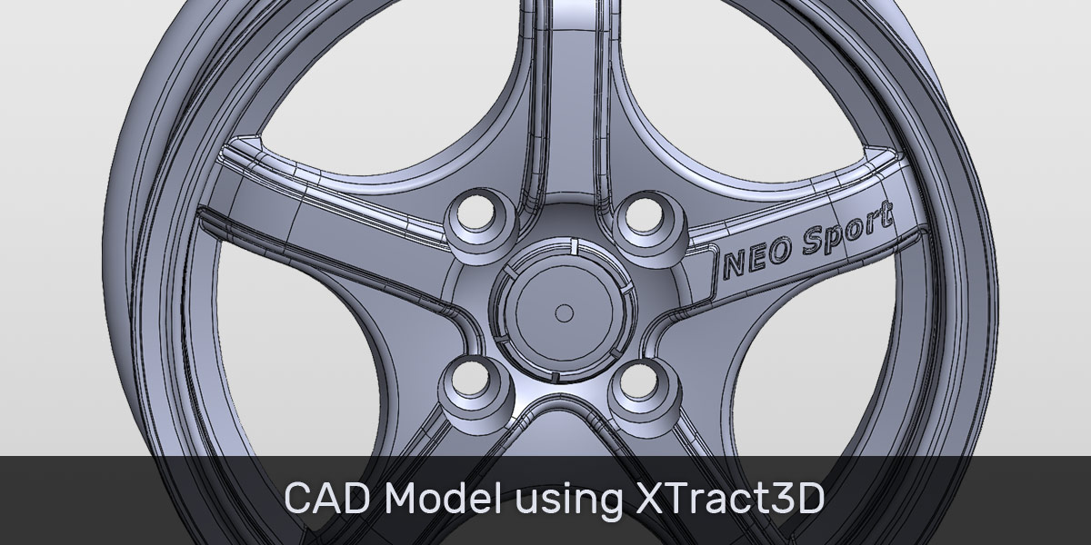
Armed with this intelligence, you can use it to replicate the part or create a new design based on the original. 3D scan data serves as a visual guide for sketching the CAD drawing. It’s pretty much tracing right on top of the scan data. You want to start the CAD drawing with tracing basic 2D sketches along with creating standard relationships and constraints in order to maximize control over how your design is developed. 2D sketches are then converted into 3D features. You continue to build out all the part’s features until the final CAD model is created like the example below.

There’s no magic button for converting a 3D scan data into a usable CAD file automatically. But there is a standardized workflow that makes reverse engineering a straightforward process.
Let’s examine this workflow step-by-step using an example to make our explanation more concrete.
Basic Steps to Reverse Engineering from Scan to CAD
We’ll illustrate the reverse engineering workflow with a rocket nozzle using SOLIDWORKS parametric CAD modeling software and XTract3D add-in. XTract3D allows you to do reverse engineering directly inside SOLIDWORKS.