

Step 2
Planning
It’s a mental process of figuring out the steps you’ll need to take before you begin 3D modeling. It involves deciding which the features need to be created separately by splitting the part up into major modeling phases in sequential steps. This step is important because with good planning, you will build a robust parametric model that creates less work—and less headaches—for you later on.
The nozzle is symmetrical part so we will use this to our advantage.
The Plan:
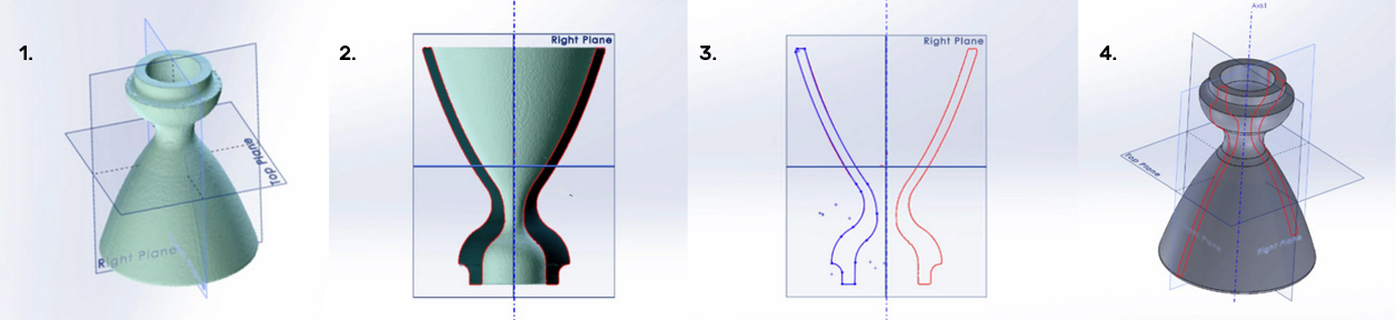
- Create a new coordinate system (It makes it easier for you to reverse engineer your part in later steps)
- Slice the nozzle in half to view the 2D cross-section of the part
- Sketch the contour of the scan data outline
- Revolve the part to get the final 3D solid CAD model
Basic 2D cross-section forms the basis of all mechanical 3D drawings. Doing the basic steps right creates a strong foundation that enables everything that happens downstream to be stable.
Tip on planning: Figuring out the true design intent
The main reason for reverse engineering is to remake the part. Therefore, the purpose is to create a ‘perfect’ part representing true design intent. This may require a detailed understanding of the function of the part because only then can the design intent be correctly interpreted.
It’s important to remember that all manufactured parts have some sort of imperfections due to the way it’s manufactured and they might have been damaged due to wear and tear, which masks the original design intent. Modeling in every single defect can be time consuming, expensive, and unnecessary. Typically the part will be remodelled to capture the design intent and to ignore the imperfections.