3D Scanning Flat Objects
At Polyga, people often email us about 3D Scanning problems that they run into when using their 3D scanner. One of the more interesting questions is when people run in to issues aligning their scans when scanning flat objects. Scanning a flat object sounds simple enough but can be particularly difficult for even experienced 3D scanning technicians.
The Problem with Flat Objects
The process of 3D scanning different objects can vary greatly, depending on the size, shape, and surface properties of the object. Flat objects have their own unique set of challenges as these objects lack the control geometry necessary to align multiple scans. Generally, for a successful 3d scan alignment, you need a roughly 30% surface to surface overlap between two different scans. In addition, you want plenty of interesting features that have least 3 different dimensions of control. For an object that’s flat, you often don’t have this.
In addition, the other challenge with flat objects is that the surface of the object itself is relatively featureless, there’s not enough interesting geometry for the alignment algorithm to use in order to perform an alignment. Even if there is interesting geometry, you may not have enough of it.
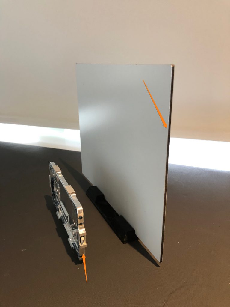
We’ll look at two examples of objects. The first one is a flat metal sheet, while not realistic, illustrates the problem nicely. You can see that if you scan this, you would get a lot of data on the front and back side of the panel, but with tiny amount of geometry on the edges to align the two sides together. Another problem is that the edge doesn’t have any interesting geometry, so the edges would slide around and not correctly line up.
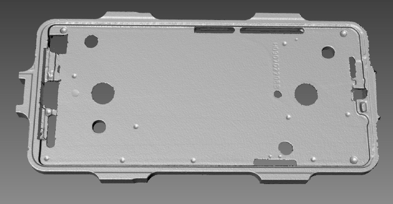
The 2nd example is a metal mount from a cell phone, and you can see how the problems described in the flat metal sheet would also apply to this more real-world example.
How to Scan Flat Objects
Most users try to solve their problem by using alignment markers, however, while you get some initially encouraging results, going this route will ultimately not work. By placing a series of simple, removable dot markers on your object, you will be able to create fixed points of reference and will allow you to do some initial alignment. However, further fine alignment will then fail as the scan is will lack geometry features to allow a successful fine alignment.

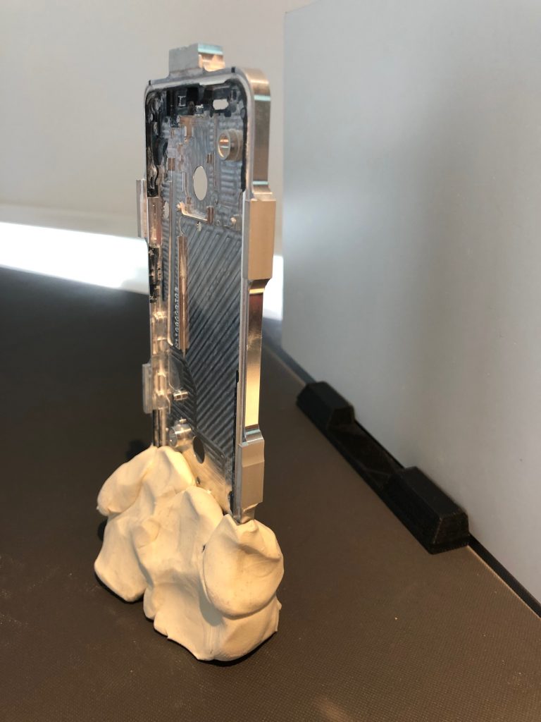
The simplest solution is to add additional 3D geometry to the sides of the edges of the object and to align using that geometry. A common practice is to use modelling clay or create some sort of geometric fixture. In our experience, for one-off scanning, modeling clay works great.
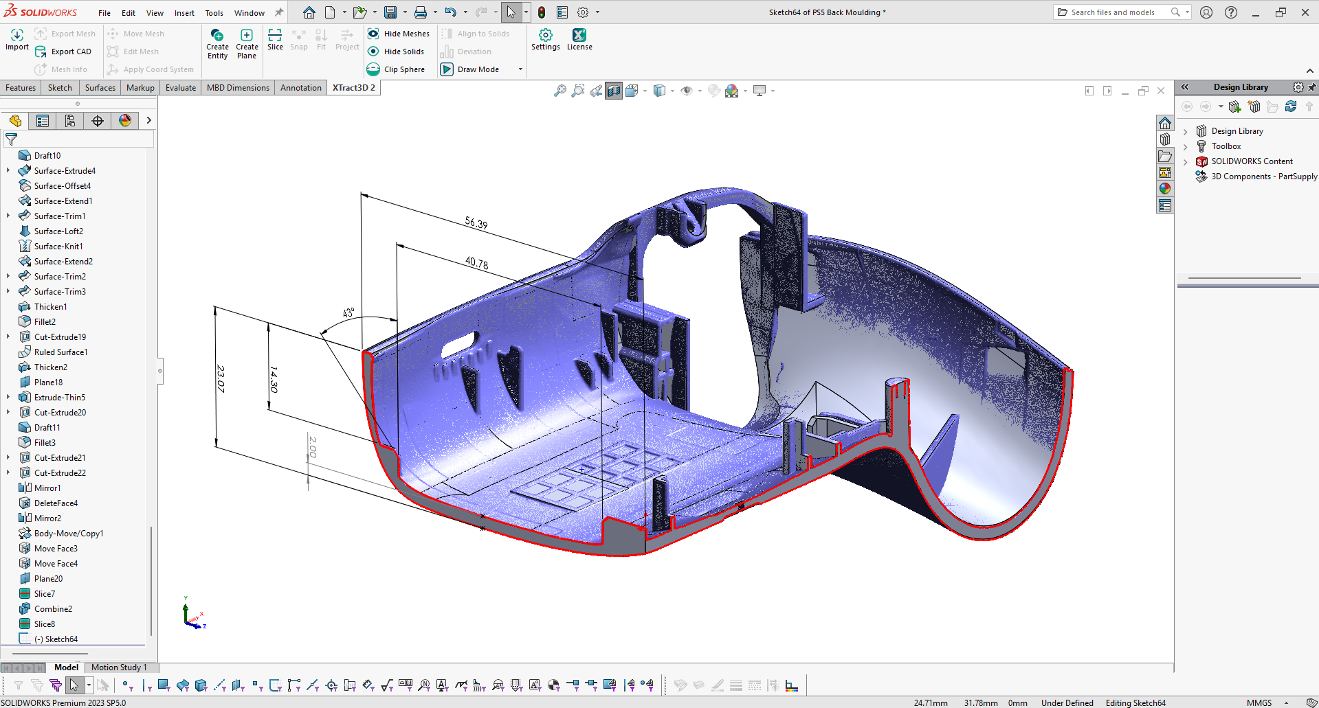
When you do the alignment of the two sides of a flat object, you can align using the features found in the modeling clay. You can then delete the geometry away before moving forward. If you need the data from the area where the modeling clay was, you would then need to remove the clay, and then add another scan to fill in the covered area. When you’re done, you’ll have complete scan that looks like this